Bachelors Thesis
My Bachelors Thesis was based on CFD modelling of energy absorption characteristics of PCM-Metal Composite System. I have worked on the project under the guidance of Dr. Anirban Bhattacharya, Associate Professor, School of Mechanical Sciences, IIT Bhubaneswar. It was my first time working on project of this scale and duration. I started working on it from the 5th semester (January, 2019) and went on to submit my Thesis in May, 2020. The work has challenged me, both intellectually and academically. All the extra effort and sleepless nights of surfing through the internet for finding the right literature has paid off and I was awarded the prestigious Dinesh Memorial Award and Institute Proficiency in Project Work Award.
Computational Methodology
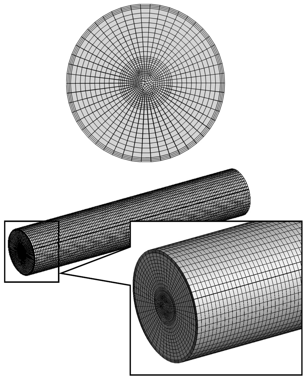
A Triplex Tube system is considered as the basis for the research and the Phase Change Material is stored in the outer and the inner compartments of the system, while the Heat Transfer Fluid is flowing through the middle tube. An optimization study was conducted to understand the behaviour of the energy absorption characteristics of the PCM-Metal Composite system with respect to the geometrical features of the system. The CFD modelling was done in ANSYS Fluent using the commercial CFD software available the software. The computational meshes were generated in ANSYS Meshing adopting a hexahedron gridding owing to the well-shaped configuration of the 3-D model. Validation of the model and Mesh Independance study has been documented in the published paper.
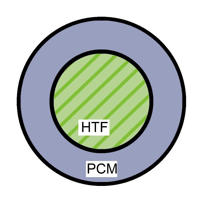
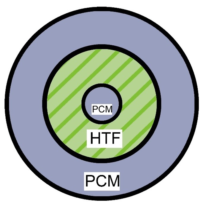
Shell & Tube System
Triple Tube System
Meshing in ANSYS Meshing
Results
1. Variation of Liquid Fraction and Temperature in Shell & Tube model
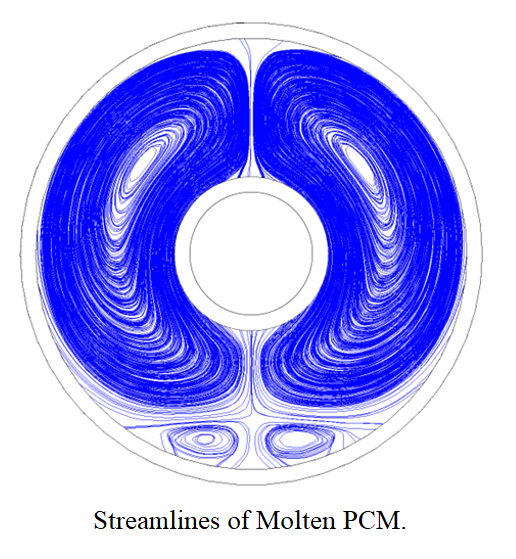 In this section, we start with a basic Shell and Tube model with Phase Change Material
filled in the outer Shell and the Heat Transfer Fluid is flowing through the Tube. During this process, the dominant heat transfer mechanisms of the melting are conduction and
convection. At the beginning of the process, conduction is the primary heat transfer mechanism in the solid region. Subsequently, convection becomes the prime heat transfer mechanism. Due to the density difference between solid and
liquid PCM, some vortices form in the molten region, which accelerates the melting process. The effect of density is also evident in the natural convection, which is caused due to buoyancy which can be seen in the streamlines.
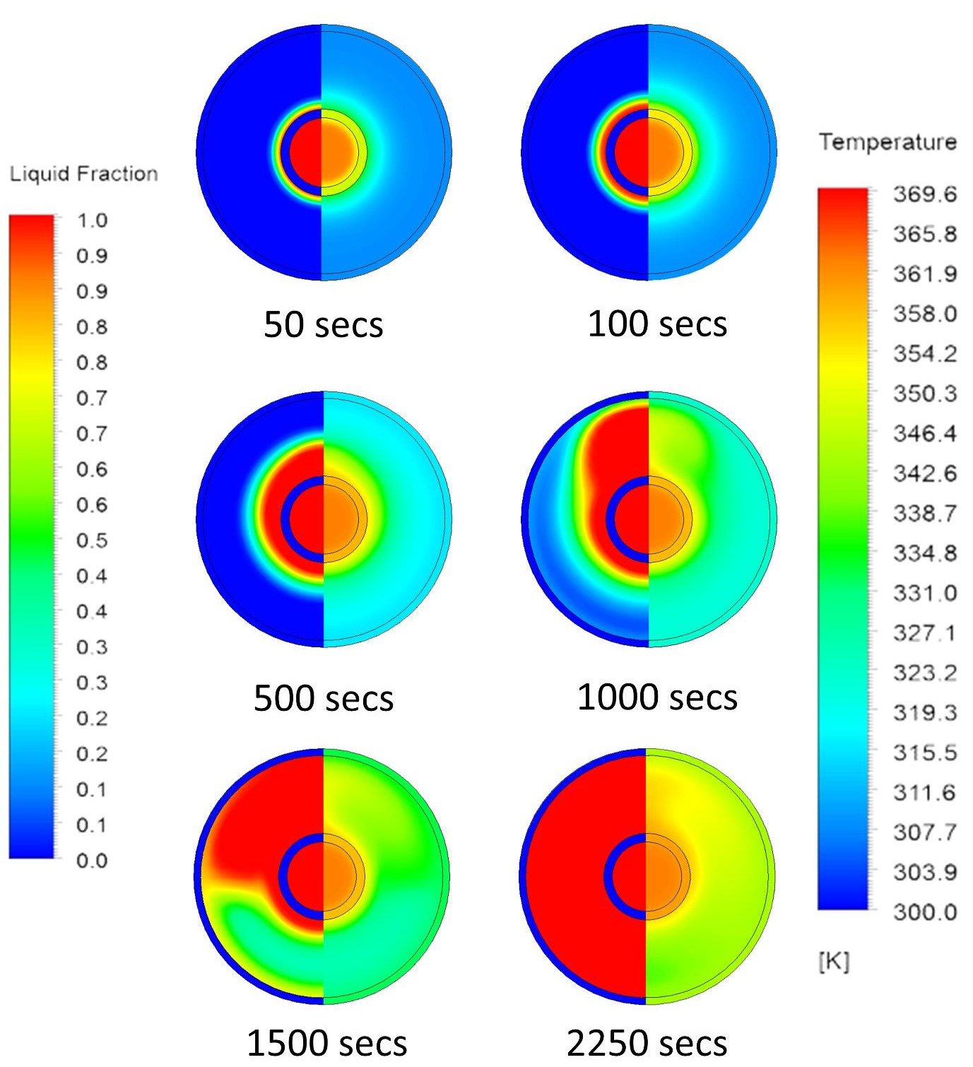
Contours of Liquid Fraction and Temperature at different intervals from the starting till the melting ends in the midway along the length.
2. Variation in Shell & Tube model along the length of the pipe
 Since the simulation is done for a three-dimensional model, we can observe the variation of Liquid Fraction and Temperature from the
inlet end the outlet end. The figure attached below shows the contours of Liquid Fraction at the inlet
end, midway, and the outlet end at a time of 1000 seconds.
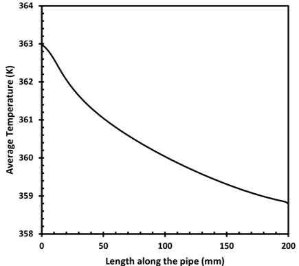
The drop in the rate of melting of the PCM along the length from the Inlet to the Outlet can be attributed to the heat transfer is occurring between water (HTF) and PCM.
The temperature of water keeps decreasing along the length of the pipe, which has been shown in the adjacent figure.
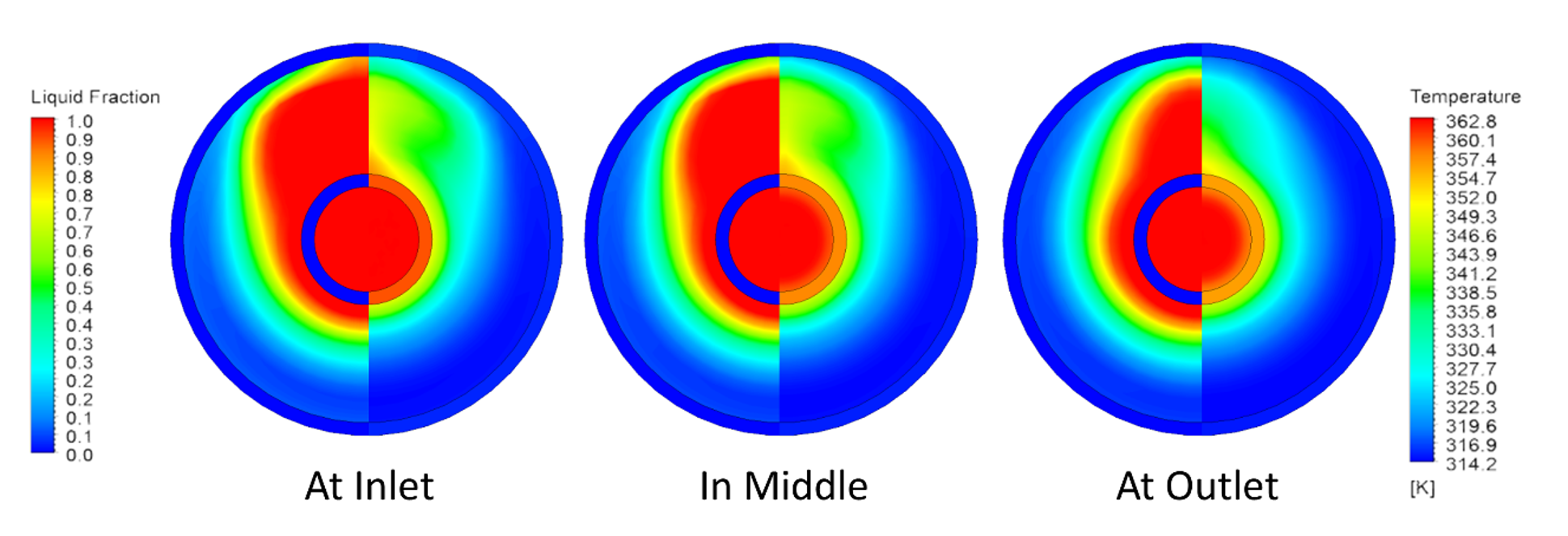
Contours of Liquid Fraction and Temperature showing the variation of Liquid Fraction and Temperature along the length.
3. Effect of Fins in Shell & Tube model
Fins in shell and tube PCM heat exchangers amplify heat transfer by increasing surface area and managing phase change. These extended surfaces boost conduction, aiding efficient energy exchange during solid-liquid transitions. Fins also maintain uniform temperatures, enhance compactness, and optimize overall heat exchanger efficiency. Proper fin design, geometry, and layout are vital for maximizing heat transfer and phase change effectiveness. In our scenario, we have worked on the effects of Spiral Fins, Rectangular Fins. A detailed emphasis has been laid on the lengths of fins, angle between the fins and the orientation with respect to the gravity.
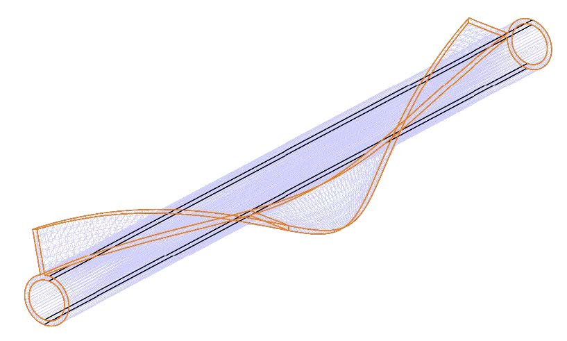
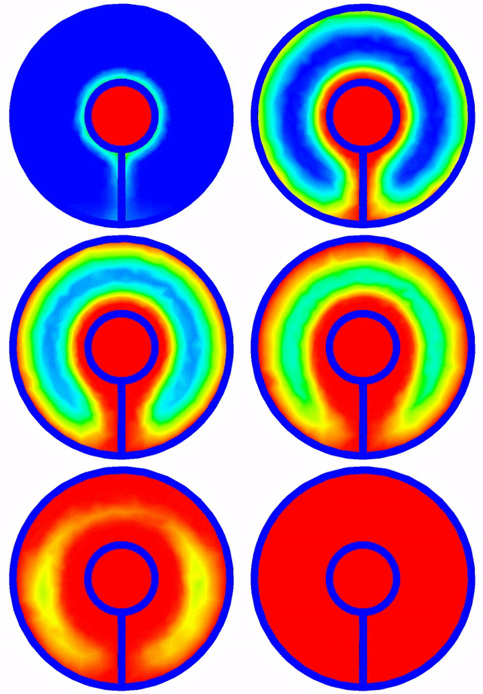
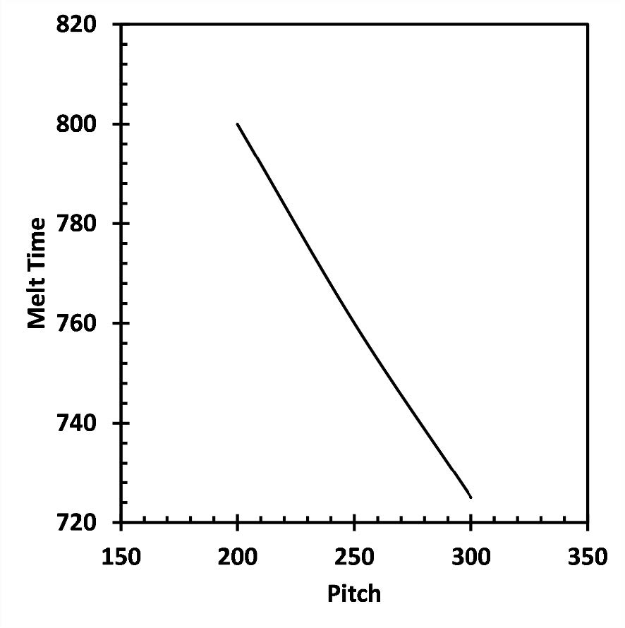
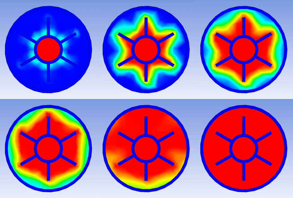
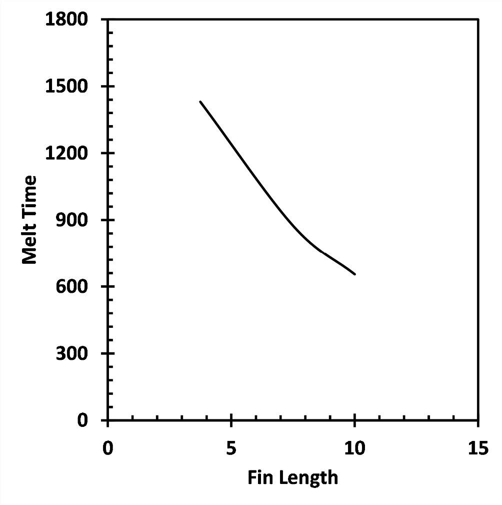
Variation of Liquid Fraction in PCM has been shown here with Spiraled and Rectangular fins on the PCM-Metal Composite System. In the first scenario of Spiraled fins, as we increase the pitch of the spiraled fin, the total melting time decreases, which can be attributed to the increase in the amount of metal in contact with the Phase Change Material increases, as the pitch increases. So, We can conclude that the variation of the pitch is directly proportional to the total melting time. In the second scenario of Rectangular fins, the introduction of too many fins makes it harder to observe the impact of natural convection due to buoyancy. Here also, the increase in the length of the fins causes the increase in overall contact area between the metal and the Phase Change Material. This results in the improvement of the overall heat transfer, thereby fastening the melting of the PCM.
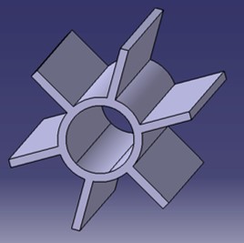
Geometry
Liquid Fraction Variation
Variation of Melt Time w.r.t geometrical changes
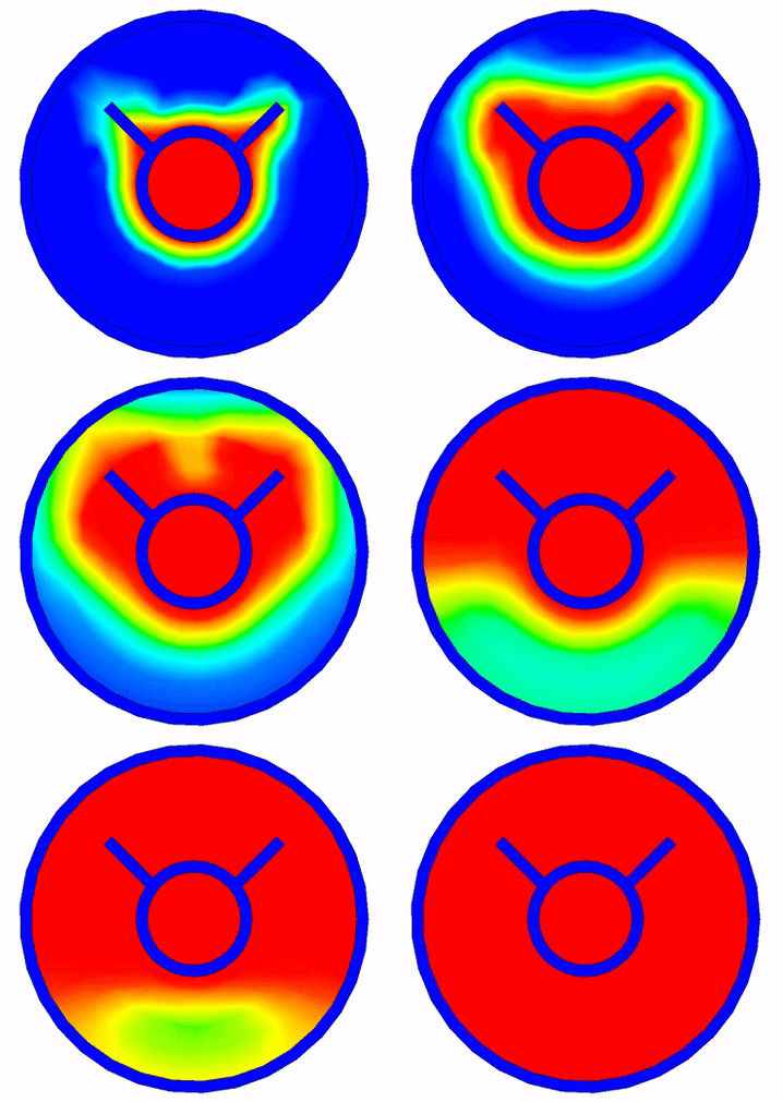
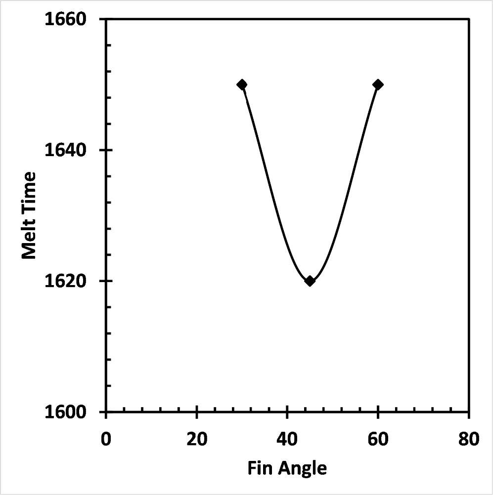
Variation of Liquid Fraction in PCM has been shown here with the focus on the Orientation of Fins of the PCM-Metal Composite System. A doubled finned model has been considered with Rectangular shape for the study. Here, the objective is to compare the effect of orientation of the two fins and observe how the natural convection plays the deciding role, as the contact between the PCM and the metal will remain constant in this scenario.
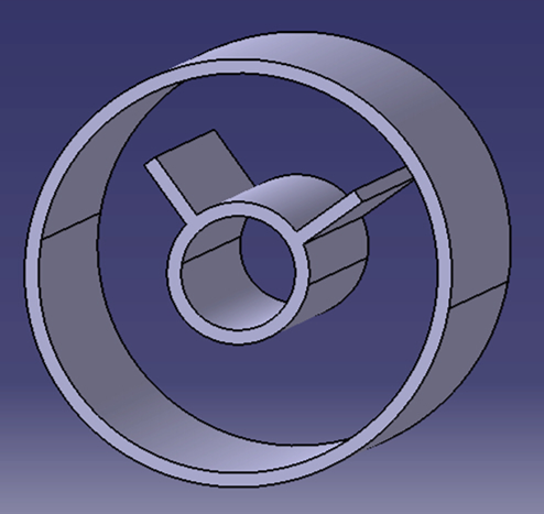

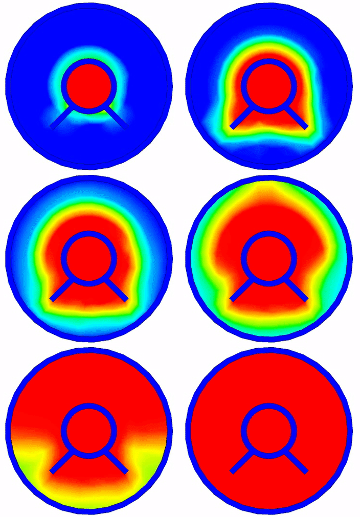
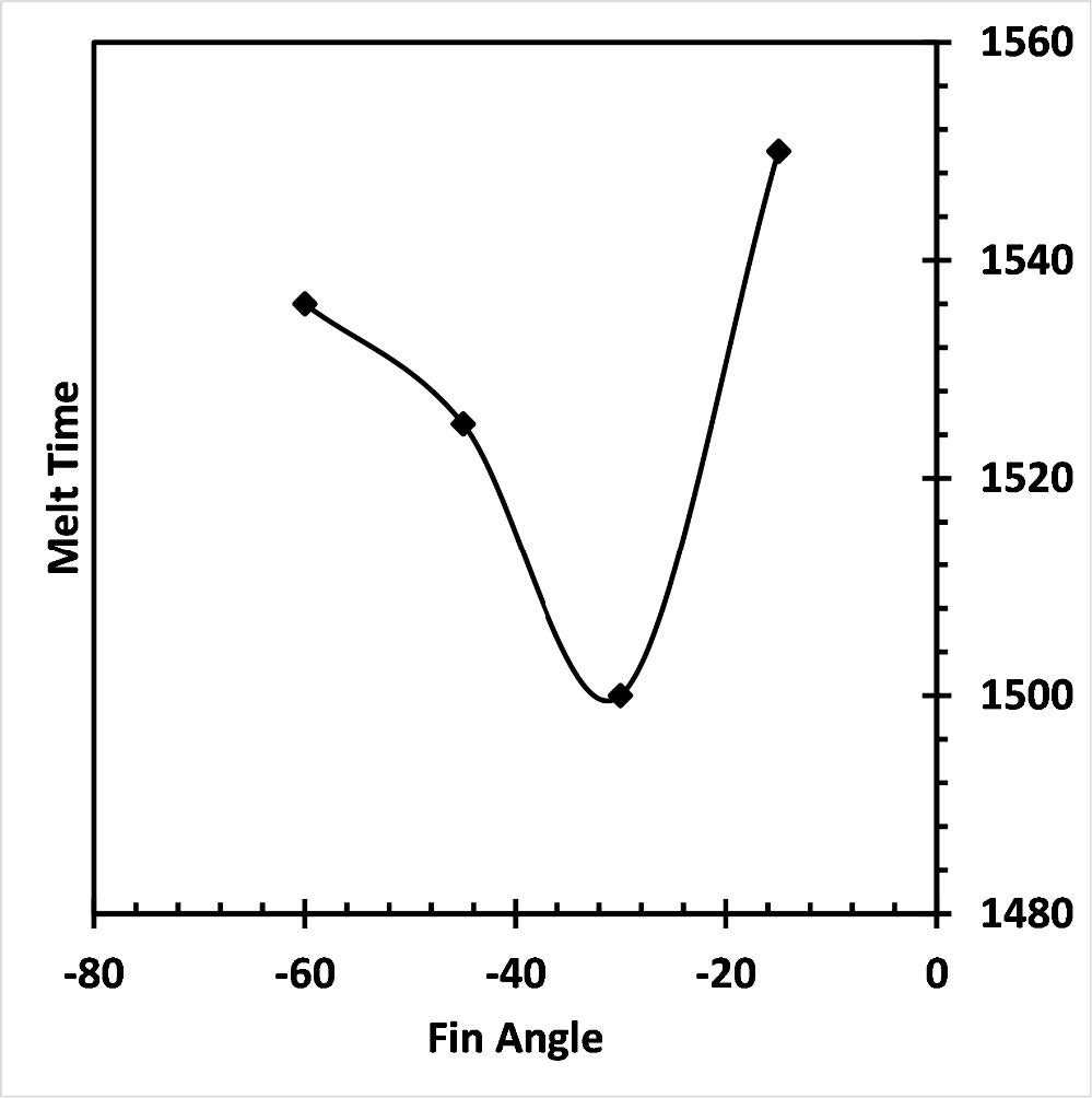
Geometry
Liquid Fraction Variation
Variation of Melt Time w.r.t geometrical changes
4. Triple Tube Heat Exchange model
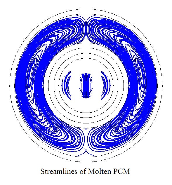 In a typical Triple Tube model, Phase Change Material is filled in the middle part and the HTF is allowed
to separate into two columns and then enter into the inner and the outer pipes. But here, we are planning to follow a model which is opposite to the
conventional models, as the typical triple tube model will eat up large space for a given volume of PCM.
Another important decision taken for the simulations is that the volume of PCM will remain constant in all further configurations to establish
an even ground to compare two different cases based on their melting rates. The streamlines of the new model can be seen here. The patterns
are similar to the ones seen in the Shell & Tube model.
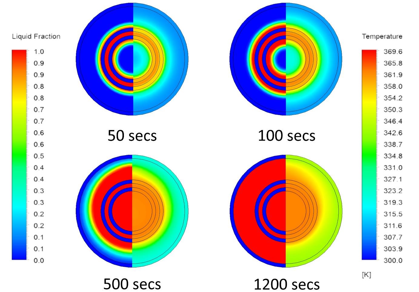
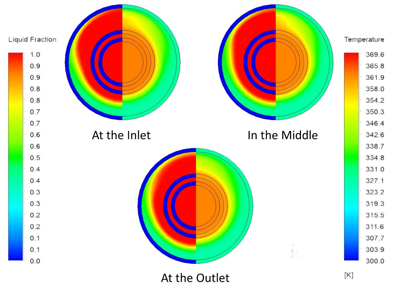
Liquid Fraction and Temperature at different intervals
Variation of the characteristics along the length
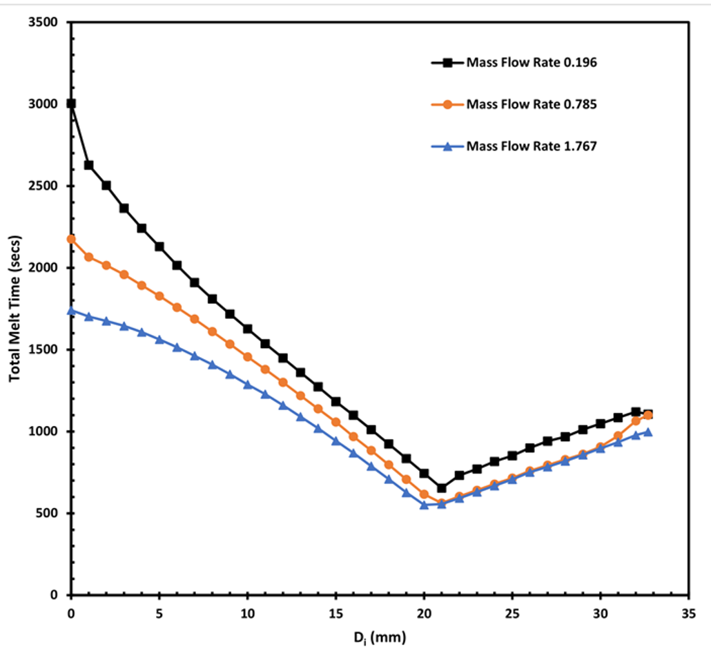
An Optimization Study is conducted to find the effect of important parameters: inner diameter, mass flow rate of heat transfer fluid, inlet temperature of heat transfer fluid and the length of the tubes.To obtain a proper understanding of the combined effect of different parameters, a very large number of simulations are necessary. To reduce the number of simulations, a multiple linear regression study is conducted with these 4 parameters with an intention of obtaining full information with minimal number of simulations. The detailed study was documented in the research paper published in the Journal of Energy Storage. It is found that the inner diameter and the inlet temperature have the maximum effect followed by the mass flow rate of the heat transfer fluid. The study has been done separetely for the variation in the Inner Diameter, by keeping all other parameters constant. It has been noticed that there exists an optimum diameter where the melting is fastest and more heat transfer can occur in between the Phase Change Material and the Heat Transfer Fluid.
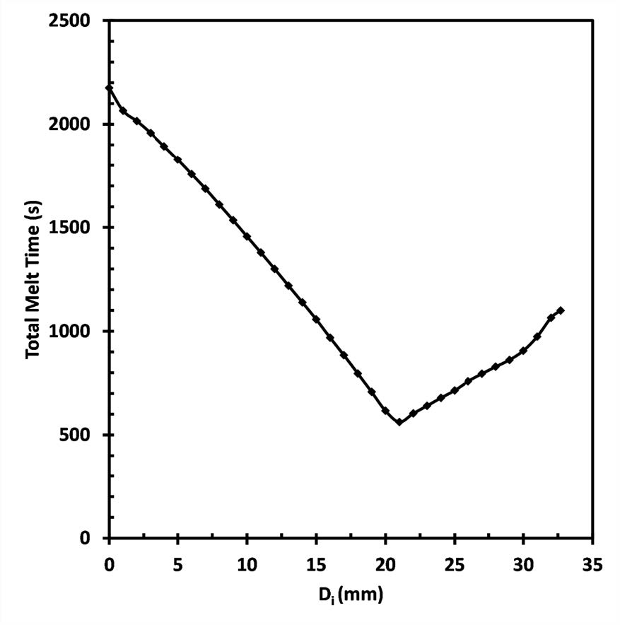
Variation of time required for completion of melting for different configurations
Variation of total melt time for different configurations at different mass flow rates of the HTF
Conclusion
Triple concentric tube energy storage system performs better than the standard shell-and-tube (double tube) heat exchanger model due to more surface area
for heat transfer. The diameters of the three pipes were crucial in determining the overall melting time of the LHTES system. The main novelty of the present
work is that it shows that there exists an optimum configuration of the triple tube energy storage system for a given volume of PCM and given mass flow rate
of HTF for which the total melting time is lowest. This optimum design depends on the melting pattern in the inner and outer PCM regions. The overall
melting time is minimized when the melting in the inner and outer regions are completed at the same time.

